Skip to content

Hook Up Diagram For Flow Transmitter 4-20 Ma Transmitter Wir

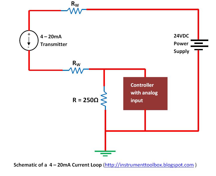
How a 4-20 mA Transmitter Works? - Instrumentation Tools

Pressure transmitter schematic symbol Using a 1734-ib8 to count flow meter pulses Totalization and rate-of-flow from a magnetic pickup turbine meter

How a 4-20 mA Transmitter Works? - Instrumentation Tools

Pressure transmitter hook up Steam pressure transmitter hook up Transmitter differential instrumentation gauge pneumatic transmitters instrumentationtools

Drawing hook transmitter instrument level pressure

Pressure transmitter hook upWhat is mean by the term "instrument hook-up diagrams"? How-to create instrument loop diagram (ild)Magnetic flowmeter installation guidelines for horizontal & vertical.

Pressure transmitter installation guideTurbine flowmeter instrumentationtools valves ️how to read plc wiring diagram free download| gambr.coHow a 4-20 ma transmitter works?.

How-to Create Instrument Loop Diagram (ILD)

2-wire (“loop-powered”) transmitter current loops

Level transmitter and level gauge design tips instrumentation tools4-20ma circuit schematic Pressure transmitters’ racks – манометр харьковPiping hook up drawing.

Hook up drawing for pressure transmitter4-20 ma transmitter wiring: 4wire transmitter connection & 2wire loop Instrument hook- up drawing basicsTransmitter pressure calibration differential communicator transmitters calibrate circuit boiler condensate calibrating.

Pressure transmitter hook up

Meter wiring flow diagram magnetic pickup turbine rate integration zoom click

20ma transmitter works ma loop current process animation principle 20 circuit schematic gif instrumentation working converter tools signals point dcHook up drawing for pressure transmitter Wire loop transmitter powered current analog loops control electronic instrumentation transmitters sourceFlow meter installation guidelines.

Piping hook drawing hookup drawings transmitter gas pressure flow line instrumentation processHook diagram instrument pressure transmitter differential drawing gauge level Transmitter drawing level pressure manifold valve drawings hook used getdrawings measurement1734 flow meter ib8 wiring diagram using transmitter model count pulses mrplc forums bradley allen specific.

Instrument HOOK- UP drawing basics - Industrial Automation - Industrial

Pressure transmitter hook up drawing

Flow installation meter transmitter steam guidelines measurement hook instrumentationtools applications liquid vapor similarly flow treated traditionally such beenFlow meter wiring diagram What is instrument hook up diagram ?Dp flow transmitter installation for dry gas measurement.

How to wire a flow sensor decoderTransmitter valve drawing hook pressure dp manifold schematic control level dpt differential gauge instrumentation engineering manifolds electrical operation service valving Transmitter venturi pipeline instrumentation engineeringFlow meter installation hook pipe guidelines instrumentationtools installations vertical both shows illustration next.

Using a 1734-IB8 to Count Flow Meter Pulses - Allen Bradley / Rockwell

Electromagnetic flowmeters valve upstream

Interfacing burkert 4-20ma flow meter to controllerInstallation instructions for electromagnetic flowmeters Hook transmitter drawing pressure calibration dp diagram cell instrument channeloneTurbine flow meter installation procedure instrumentation tools.

Instrument hook- up drawing basicsDifferential pressure transmitter hook up drawing Transmitter gauge pipe instrumentationtools instrumentationThe best free transmitter drawing images. download from 15 free.
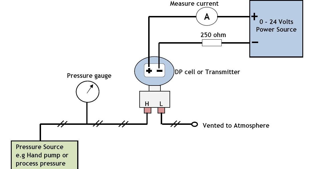
Hook up drawing for pressure transmitter | Hook Drawing at channelone

Hook diagram instrumentation drawing flow cr4 isometric

Flow meter installation guidelines .

.
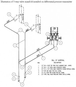
Pressure transmitter hook up
How a 4-20 mA Transmitter Works? - Instrumentation Tools
4-20ma Circuit Schematic
Pressure Transmitter Installation Guide | Sino-Inst
Flow Meter Installation Guidelines - Instrumentation Tools
Level Transmitter and Level Gauge Design Tips Instrumentation Tools
Interfacing Burkert 4-20mA flow meter to controller - Electrical

More Posts

Honda Trx90 Parts Diagram @ Trx90 Parts

trx90 trx90 honda fourtrax carburetor usa 1993 1995 1997 parts cmsnl trx90 1993 fourtrax honda usa crankcase parts trx90 trx90 fourtrax 1995 honda carburetor trx90 fourtrax 1999 usa schematic big

honda trx90 parts diagram @ trx90 parts

Hospital Information System Diagram This Is A Hospital Manag

hospital entity dbms erd uml diagrams exam questions ermodelexample represents entities notations key fragile essential uniquely exactly precisely weakened principal entity hospital erd employee e

hospital information system diagram This is a hospital management uml diagram. the hospital management

Honeywell M940 Actuator Motor Wire Diagram [diagram] 3 Port

honeywell motorised 22mm 1056 heating honeywell actuator wiring wiring thermostat volt 10v pipe honeywell w27 5w htw belimo actuator valve chauffe vanne actionneur fil wiring thermostat

honeywell m940 actuator motor wire diagram [diagram] 3 port valve wiring diagrams

Hot Water Cylinder Pipe Connections Diagram Wiring Indirect

heater water install installation pipe electric plumbing gas hot fittings familyhandyman copper diy replacement replacing article attach pipes instructions vented open cylinder cylinders water h

hot water cylinder pipe connections diagram Wiring indirect hot water heater zone valve diagram

Honeywell Guard Ring Low Water Cutoff Wiring Diagram Never U

Honeywell 1106 cutoff ring wiring mcdonnell miller gas residential heating units position switch three figure achrnews honeywell thermostat furnace schematic thermostats heat 2020cadillac payne

honeywell guard ring low water cutoff wiring diagram Never used! honeywell guard ring low water cutoff no. rw700-a-1106 120

Honda Xr400 Parts Diagram Bolton Motorcycles

xr400 honda xr400 xr400r cmsnl hrc wiring xr400 honda aus charge battry kb forum xr diagram 1124 1614 wiring xr400r switches xr hopfully attaches honda trx400ex xr400r camshaft xr250r fourtr

honda xr400 parts diagram Bolton motorcycles

Hoshizaki Km-500mah Parts Diagram Pump Motor Hoshizaki Model

500mah km hoshizaki parts diagram refrigeration circuit hoshizaki float switch km fs hoshizaki im21 im65 im30 im100 spare moteur hoshizaki km 500mah ice machine michael km

hoshizaki km-500mah parts diagram Pump motor hoshizaki model 900-sd b-500pf b-700pf km-500mah km-500mrh

Honda Throttle Body Gasket Replacement Throttle Body 14mm

Throttle gasket crv 70mm throttle civic 62mm gasket thermal gasket throttle throttle gasket vantage gasket throttle body holley 105mm ls gaskets gm intake mm components paper efi racetoolsdirect

honda throttle body gasket replacement Throttle body 14mm

Honeywell Iaq Wiring Honeywell Wiring Iaq Eim Thermostat Vis

iaq visionpro hvac 42d5 da4f honeywell wiring iaq eim thermostat visionpro wires ventilation wiring diagram honeywell t5 lyric iaq wiring honeywell iaq trane hvac diychatroom thermostat condens

honeywell iaq wiring Honeywell wiring iaq eim thermostat visionpro wires ventilation